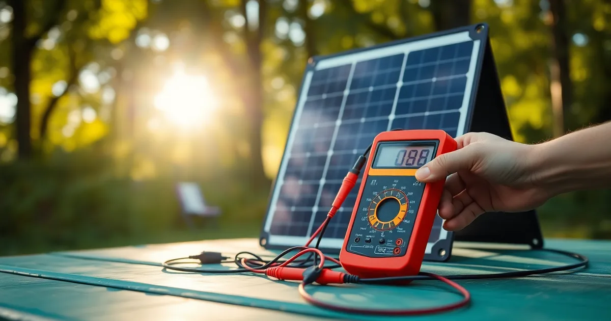
A portable power station that refuses to charge from solar is almost always a voltage, polarity, or port-limit problem, not dead hardware. Check the panel's open-circuit voltage first, then MC4 polarity, then the station's input specs, before you return anything.
Most stations need somewhere between 15V and 18V DC at the solar input before the MPPT controller wakes up and starts pulling current. A single "12V" folding panel looks like it clears that bar, and on a multimeter it usually does, reading 18V to 20V open-circuit in full sun. Put it under load on a hot afternoon and that number sags. Panel voltage drops roughly 0.3% to 0.4% per degree Celsius above 25C, so a 60C panel surface can lose 10% or more of its open-circuit voltage exactly when you need it most. The station sees a number below its startup threshold and reports nothing.
The other silent failure is polarity. MC4 is a standard, not a guarantee. Extension cables, Y-branches, and third-party adapters get wired backwards more often than anyone admits, and a reversed pair usually produces a cheerful "no input" or a flat 0W reading with no error code at all. A $20 multimeter settles it in ten seconds.
Then there is the limit nobody reads in the manual. A 200W max input port fed by 400W of panels will not charge faster; many units simply stop charging to protect the input stage, and some cap current at 10A regardless of wattage.
- Startup threshold matters: most portable power stations need 15-18V DC minimum at the solar input before MPPT charging begins, so a single 12V panel sitting at 18V open-circuit can fall short under load.
- Reversed MC4 kills quietly: swapped positive and negative pins from an adapter or extension cable typically show "no input" or 0W on the station display, with no fault light.
- Input limits cut power: exceeding a port's rated maximum, commonly 200W or 10A on mid-size units, triggers a protective shutdown rather than a faster charge.
- Shade hits strings hard: partial shading on one panel in a series string can drop total output by 50-70%, sometimes below the MPPT minimum voltage.
- Multimeter before blame: verify open-circuit voltage and pin polarity at the cable end that plugs into the station, since the fault is usually in the cable, not the panel.
Is your solar panel voltage high enough to wake up the MPPT?
A 100W folding panel rated for "12V systems" does not put out 12V. Unfolded in full sun with nothing connected, it sits around 18–20V open-circuit — that is Voc, the number printed on the spec sticker — and sags to roughly 15–17V the moment the station starts drawing current (Vmp). That gap matters, because an MPPT charge controller has to see a minimum input before it will begin tracking at all. On most 2026 portable stations that startup threshold lands between 15V and 18V. Feed it 13V and the controller does not "charge slowly." It does nothing, and the screen shows zero watts with no error message, which is exactly why people assume the hardware is dead.
Measure it yourself before you buy anything. Set a multimeter to DC volts, put the probes across the panel's output — male pin positive, female negative on an MC4 pair, and you should read positive volts; a negative reading means the leads are reversed or the panel is wired backwards, both of which will stop charging on stations that police polarity. Then compare that number to the manual's solar input window for your specific unit. A Jackery Explorer 1000 accepts up to 200W at 25V max and 10A max; an EcoFlow Delta 2 and a Bluetti AC200P have their own ceilings, and none of them publish a "minimum" prominently. If your Voc in direct sun is 17V and the station wants 18V to start, you are 1V short, and no amount of repositioning the panel will close that gap.
The two ways to fix an undersized voltage
Wire a second identical panel in series. Series adds voltage and keeps current the same, so two 18V panels become roughly 36V — but check the station's max input voltage first, because 36V into a 25V-limited Jackery Explorer 1000 is a good way to end a trip early. The alternative is buying a single higher-voltage panel, which is cleaner for a van roof but costs more than the second foldable. Parallel wiring is the wrong move here: it doubles current and leaves voltage where it was, so the MPPT still never wakes up. Cable length deserves a mention too — 14AWG loses roughly 0.5–1V per 10m, so a 15m run from a roof panel to a station inside the van can drop you below threshold on its own.
If your Voc checks out at 19V in the open but the station still shows nothing, the problem has moved downstream of the panel. Series strings also collapse under shade: covering one panel in a two-panel series run can cut total output by up to 70%, and if that shaded voltage dips under the controller's startup floor, charging stops entirely rather than tapering. Test each panel alone in full sun before you blame the pair.
How to check MC4 polarity and avoid a dead short
Do this before you connect anything to the station's input port. You need a multimeter set to DC volts (20V or 200V range is fine), sunlight on the panel, and two minutes. If you don't own a meter, a US$15–25 unit from Klein, AstroAI or Uni-T is the best money you'll spend on a solar kit; guessing polarity is how people fry input fuses.
MC4 is the connector standard on nearly every folding panel from Renogy, Jackery, Bluetti and EcoFlow. The convention is fixed: the male pin (the one with the exposed metal rod) carries positive, the female socket (recessed) carries negative. Manufacturers still get this wrong at the factory, and DIY cable repairs get it wrong constantly.
- Disconnect the panel from the power station. Nothing should be plugged into the solar input port while you test.
- Lay the panel flat in direct sun. No shade on any cell — even a hand's shadow across one corner will pull the reading down. A Renogy 100W panel should show roughly 18–20V open-circuit (Voc) in full sun.
- Set the multimeter to DC volts. Touch the red probe to the metal pin inside the male MC4 connector. Touch the black probe to the metal contact inside the female connector. Hold both steady — the contacts are recessed and it's easy to miss them.
- Read the display. You want a positive number, typically 18–20V for a 100W panel. If it reads negative, your polarity is reversed relative to the MC4 convention, and the station will either refuse to charge or blow its input protection.
- If the reading is negative, you have two fixes. Cheapest is an MC4 polarity adapter (US$8–15, sold by Renogy and generic sellers on Amazon). Cleaner is to release the pins with an MC4 spanner tool (US$10) and swap them inside the housing.
- Re-test after the fix. Same probes, same positions, expect positive voltage. Takes 30 seconds.
- Only now connect to the station. Watch the display: charging should start within 5–10 seconds on a Jackery Explorer 1000 or EcoFlow Delta 2 if input voltage clears the MPPT threshold. No reaction means the voltage is below the controller's startup point, not that polarity is still wrong.
- If you're running two panels, test each one separately before joining them in series or parallel. One reversed panel in a series string drags the whole array's voltage below the MPPT threshold and produces the exact symptom you're trying to diagnose.
One measured figure worth knowing: a 100W panel rated 18–20V open-circuit typically sits at 15–17V under load. That's the number the MPPT actually sees, and it's often 1–3V below the 15–18V startup window on 2026-model stations. Testing Voc alone tells you the panel works; testing while connected tells you whether it will actually wake the controller.
The failure mode when polarity is wrong and the station doesn't have reverse-protection diodes: you hear nothing, see nothing, and the input fuse opens silently. Jackery and EcoFlow units mostly survive this. Cheaper stations with automotive-style fuses usually don't, and the fuse is soldered to the board on some models — a US$200 repair for a US$10 mistake.
Are you exceeding the solar input wattage or amperage limit?
Almost every portable power station spec sheet lists three solar limits, not one: a maximum wattage, a maximum open-circuit voltage, and a maximum input current. The Jackery Explorer 1000, for example, caps solar input at 200W, 25V, and 10A. Cross any of those and the charge controller either derates hard or refuses the array entirely, which the user experiences as "nothing is happening."
The three limits are not equally forgiving. Volts are a hard ceiling. Push 30V into a 25V input and you can damage the controller's input capacitors, and several brands void the warranty on that basis alone. Amps are softer: exceed the 10A limit with a 12A array and most 2026-model stations simply clip the excess, wasting the extra panel rather than failing. Watts sit in between, since over-paneling a 200W input with 400W of panels usually just means you never see more than 200W.
| Station (model year) | Max solar input | Max Voc | Max input current | MPPT startup threshold |
|---|---|---|---|---|
| Jackery Explorer 1000 (2021) | 200W | 25V | 10A | ~16V |
| EcoFlow Delta 2 (2022) | 500W | 60V | 15A | ~15V |
| Bluetti AC200P (2022) | 700W | 150V | 12A | ~16V |
| Renogy 100W panel (single) | 100W | ~20V Voc | ~5.5A | n/a |
| Two Renogy 100W in parallel | 200W | ~20V Voc | ~11A | n/a |
| Two Renogy 100W in series | 200W | ~40V Voc | ~5.5A | n/a |
Read the table by station, not by panel. If you own a Jackery Explorer 1000, the 200W parallel pair is the winning configuration: 200W sits exactly at the input ceiling, 20V Voc is comfortably under the 25V limit, and 11A is close enough to the 10A cap that you lose maybe 10% to clipping on a clear day in July. The case that flips this is anyone with an EcoFlow Delta 2 or Bluetti AC200P. Their 60V and 150V input ceilings mean series wiring is the better move, because 40V on two panels stays safe and keeps current low enough that 14AWG cable runs of 10m only drop about 1V. Series only becomes the wrong answer when you cannot avoid shade: one shadowed panel in a series string can cut the whole array's output by up to 70%, while the same shadow on a parallel pair costs you only that panel's contribution.
What is pass-through charging doing to your solar input?
Pass-through charging is the feature that lets a Jackery Explorer 1000 or EcoFlow Delta 2 run a fridge or a laptop from its AC inverter while solar tops up the battery at the same time. On paper it looks like the station is charging. On the display, the solar input figure can sit at 0W or flicker between 0 and 40W, and owners assume the panel has failed. What has usually happened is that the load is drawing more than the panel is producing, so the station pulls the difference from the battery, and the charge controller decides there is nothing worth converting. You get a station that holds steady at 62% all afternoon.
Some units cut solar input entirely once the AC inverter is switched on. Bluetti's AC200P and several EcoFlow models prioritise wall (AC) input over PV when both are present, and a few firmware revisions pause PV harvesting whenever output exceeds a set threshold. Check the manual for the phrase "solar priority" or "dual charging" — if it is absent, assume the station is not doing what you think. The 10–20% efficiency loss inherent to pass-through conversion is a separate, smaller problem; the pause is the one that costs you a full day of yield.
The two-minute test
Turn off every output — AC, DC, USB, the lot — and watch the solar input reading for 60 seconds. If wattage climbs from 0 to something in the 60–90W range on a Renogy 100W panel in good sun, the panel and wiring are fine and the load was the culprit. If it stays at 0W with all outputs off, the problem is upstream: voltage, polarity, or the input limit, in that order.
There is no universal fix once you confirm load-versus-generation starvation. For a van-lifer running a 12V compressor fridge that cycles on and off, leaving outputs enabled works because the duty cycle leaves windows for solar to recover — you might lose 15% of daily harvest and not notice. For a home-backup user charging a station to full before an outage, leave everything off until the battery hits 100%, then run loads from the battery. Sequencing beats hardware every time.
Why partial shade kills series strings but not parallel
Panels wired in series add their voltages and share one current path. That single path is the problem. Put a leaf, a roof rack shadow, or a passing cloud edge across one panel in a four-panel string and its current collapses. Because the current is the same everywhere in a series circuit, every other panel in that string is dragged down to the weakest panel's output. Partial shade on one panel of a series string can cut total output by up to 70%, even though three of the four panels are in full sun.
Parallel wiring behaves differently. Each panel's current adds at a shared voltage, and a shaded panel only loses its own contribution. If your string was making 5A and one panel drops to 1A, a parallel array lands around 16A instead of 20A from four 5A panels. A series array in the same conditions can drop to roughly 5A total. Same shade, same panels, radically different outcomes.
Bypass diodes help, but they are not a fix
Most panels above 20W ship with bypass diodes across substrings. When a cell group is shaded, the diode routes current around it so the string does not stall completely. What the diode does not do is recover the shaded panel's power. A Jackery Explorer 1000 or EcoFlow Delta 2 fed by a Renogy 100W panel under half a tree will still lose 30-60% of its expected input, depending on how much of the panel is covered and whether the shade falls across a substring boundary or just clips a corner.
For a van build, that pushes the wiring decision toward parallel, or series-parallel if your controller's voltage limit allows it. Series wins on cable runs: 18-20V open-circuit per panel means less current and less voltage drop over 10m of 14AWG, which loses 0.5-1V regardless. Parallel wins on shade tolerance, and shade is the far more common enemy on a vehicle roof. If you cannot avoid parking under trees, run parallel and accept the thicker cable or shorter run. If your roof is clear and the panels sit 15m from the power station, series makes more sense.
Cable and connector losses you can measure
A 100W Renogy panel sitting in full sun puts out roughly 18–20V open-circuit and 15–17V under load. Your Jackery Explorer 1000 will not start its MPPT below about 15V on the input. That leaves you a working margin of maybe two volts, and thin cable can eat all of it. Voltage drop is not a rounding error at these levels; it is the difference between charging and a dead screen.
The formula is one line: Vdrop = current × resistance. Resistance rises with length and falls with copper cross-section, so a long thin run is the worst combination. Anything below 12AWG over five metres deserves suspicion.
- Measure the drop, do not guess it. Put your multimeter across the panel's output at the panel, note the volts, then move the probes to the far end of the cable where it enters the power station. Under load, a 1V difference on a 15V input is a 6–7% loss before the MPPT even sees it. If you read below 15V at the station while the panel shows 17V, the cable is your problem, not the hardware.
- Go 10–12AWG past five metres. A typical folding panel ships with 14AWG or thinner because it packs smaller and costs less. At 10m that 14AWG lead drops roughly 0.5–1V depending on current. Two panels in parallel double the current and therefore double the drop, so an 8A string through a 10m 14AWG run can lose more than a volt on its own.
- Inspect every MC4 joint by hand and eye. Push each pair together until you feel the click, then tug. A partially seated MC4 has high contact resistance and will warm up under load, which raises resistance further. Touch the connectors after ten minutes of charging: anything noticeably hot is making poor contact.
- Look for green in the pins. Corrosion on MC4 contacts is common on van builds where the panel lives outside. Green or white deposits mean copper oxide, which is a poor conductor. Replace the connector rather than scraping it; a new MC4 pair costs a few dollars.
- Match your connector type properly. Adapters from MC4 to Anderson Powerpole or XT60 add another joint and another point of loss. If the adapter is rated 10A and you are pushing 12A, it will fail quietly. Check the stamped rating on the housing.
- Beware the extension that came free in the box. Cheap 16–18AWG "solar extension" leads are sold everywhere and are fine for a 20W trickle panel. On a 200W array they are the single most common cause of a station that refuses to start charging at midday and works fine at 10am.
The item people most often get wrong is the last one. They buy a bigger panel to solve slow charging, then run it through the same thin extension lead, and the extra output disappears into the cable. If your station charges on a short lead and stalls on a long one, you have your answer without touching the panel or the power station at all.
Is the solar charge controller set to the right mode?
On a Jackery Explorer 1000, an EcoFlow Delta 2, or a Bluetti AC200P, the DC input is shared between the car port and the solar port. Since the earlier sections already ruled out voltage, polarity, and amperage problems, the remaining culprit is usually the setting itself: if a car/car-port mode is selected, the station caps the input around 12V and current-limits hard, so a Renogy 100W panel sitting at a healthy 18V open-circuit gets treated as a trickle source. Switch the DC input to "solar," or on models with a DC input priority menu, confirm the solar path is chosen before testing anything else.
While you are in that menu, check the firmware version. In 2023–2025, EcoFlow pushed an over-the-air update for the Delta 2 that corrected an MPPT tracking bug causing the station to remain locked at a low duty cycle when panel voltage hovered near the 15–16V startup threshold. Bluetti did the same for the AC200P's MPPT firmware after users reported that a 17V input would not wake the charger until the panel was momentarily disconnected and reconnected. Update the companion app to the latest version, then let the station sit with an active solar connection during the update; several of these fixes only apply when the DC input is energised.
If the menu looks correct and firmware is current, perform a full reset before condemning the hardware. Hold the main power button for 10–15 seconds until the display blinks or the unit powers off, release, and power back on. On models with a separate DC/AC reset or an "input reset" in the app, trigger that as well. The reset clears a latched state that can persist after a previous fault, over-temperatures, or a reversed MC4 connection the station detected and never fully cleared.
When to suspect the panel or the station is actually faulty
Once you have ruled out voltage, polarity, input limits, shade, cable losses and charge mode, the odds shift: you are now looking at roughly a 1-in-10 case where a component has genuinely failed. Isolating which one takes about 20 minutes and one multimeter. Do these in order, because each step narrows the field and you can stop as soon as you get a clear result.
- Read the panel's open-circuit voltage (Voc) directly. Disconnect everything, set the multimeter to DC volts (20V or 200V range), and put the probes on the two MC4 pins. A healthy 100W folding panel like the Renogy 100W reads 18-20V in full sun at 25°C. If you get below 16V in good sun, or under 10V, the panel or its internal bypass diodes are suspect. Spec sheets are usually printed on the back of the panel — compare against that number, not against a generic figure.
- Check for a 10% deviation, not an exact match. Voc rises in cold and falls in heat, roughly 0.3-0.4% per °C for silicon. A panel spec'd at 21.6V reading 19.8V on a 35°C afternoon is fine. Reading 14V on a cool morning is not. If you measure within 10% of the label in reasonable conditions, the panel is almost certainly working.
- Do a loaded test with a small DC load. Voc alone can look healthy while the panel collapses under current. Leave the multimeter on the panel, then briefly connect a 12V automotive bulb or a known 12V device. If voltage craters from 19V to 6V, you have an open cell string or a cracked solder joint under the laminate. That is a dead panel, not a wiring issue.
- Charge the station from its AC wall adapter. This is the single most informative test you have. If a Jackery Explorer 1000, EcoFlow Delta 2 or Bluetti AC200P charges normally from the supplied AC brick but refuses to accept solar, the battery and BMS are fine and the solar input path is the problem. That moves suspicion to the solar port, its fuse, or the internal MPPT board.
- Inspect the solar input port and its fuse. Many stations use an Anderson Powerpole, XT60 or a proprietary barrel for solar. Look for scorching, a pushed-in pin, or corrosion. Some units (the Bluetti AC200P is a known example) have an inline or board-level fuse on the solar input that is replaceable; if yours does, test continuity across it. A blown fuse gives you perfect Voc and zero charging, which matches your symptom exactly.
- Substitute one component at a time. Borrow a second panel and plug it into the same station, or plug your panel into a friend's station. Do not change both at once. If panel B charges station A, your station is fine. If panel A charges station B, your panel is fine. If neither combination works, you have two faults or a connector problem common to both — check the MC4 mating pairs next.
- Confirm with a known-good controller. If you have a standalone MPPT or PWM charge controller and a small 12V battery, run the panel through it. A charge controller that lights up and pushes current proves the panel end-to-end, isolating the fault to the power station without needing to borrow anything.
The step people skip is the loaded test. Voc looks reassuring, so they conclude the panel is healthy and start dismantling the power station — which is the one thing still under warranty and the one thing you cannot easily repair on the roadside. Voltage under load is the number that matters, and it takes ten extra seconds to get.
Frequently Asked Questions
Why does my portable power station show 0W when solar panel is connected?
Check polarity first: reverse the MC4 leads and the wattage usually appears within seconds, since most stations block reverse current silently rather than warning you. If polarity is fine, the panel voltage is likely below the station's startup threshold, typically 14-18V for a 12V system. A station also reads 0W while passing AC load straight from the wall, effectively idling its solar input.
Can I use a 12V solar panel to charge a 24V power station?
No. A nominal 12V panel puts out roughly 18-22V open circuit, and a 24V station needs at least 30V to begin charging, often 32-36V in practice. Wire two 12V panels in series to reach 36-44V, or buy a single 24V or 36V panel. Panel wattage matters less than hitting that voltage window, so two mismatched series panels can still work if their current ratings are close.
What happens if I exceed the max solar input wattage?
Most stations clip the excess rather than fail. A unit rated for 200W solar input fed 400W will typically accept around 200W and cap there, though some models shut the input down entirely and resume once voltage drops. Jackery, EcoFlow and Bluetti all publish per-model solar limits in the manual. Running 200V into a 30V-limited input is the case that actually destroys hardware.
How do I test my solar panel with a multimeter?
Set the meter to DC volts, rated for at least 100V, touch the red probe to the positive MC4 pin and black to the negative, and read open-circuit voltage in full, unshaded sun. A healthy 100W panel rates around 22V Voc and should measure within 10% of that, so 20-24V. Below 18V points to a shaded, dirty or failing panel.
Why does my power station stop charging when I turn on the AC output?
Load is beating generation. If your 60W panel feeds a station while a 200W AC load runs, the station draws the difference from the battery and solar charging pauses to protect the cells. Switch the load off, or add solar capacity above the load's wattage. Some models also disable pass-through below roughly 10% battery, so charge to 20% first.
Do I need an MPPT controller for my portable power station?
No. Nearly every portable power station sold since 2018 has MPPT built into its solar input, so an external controller duplicates the job and usually causes trouble. Stacking a second MPPT can confuse the station's input sensing and drop efficiency by 20-30%, or trigger a low-voltage shutdown. The exception is a bare DIY battery build with no integrated electronics.